<a href='/tag/trunnion-mounted-ball' target='_blank' class='key-tag'><font><strong>trunnion Mounted Ball</strong></font></a> Valve Installation Mistakes to Avoid
Trunnion Mounted Ball Valve Installation Mistakes to Avoid
Trunnion mounted ball valves are widely used in oil and gas, petrochemical, pipeline transmission, and high-pressure industrial services.
The performance and service life of a trunnion mounted ball valve depend heavily on correct installation and commissioning.
This guide explains common trunnion mounted ball valve installation mistakes to avoid and provides practical,
SEO-friendly technical guidance, checklists, specification tables, and best practices suitable for engineering teams,
procurement professionals, and plant operators.
1. What Is a Trunnion Mounted Ball Valve?
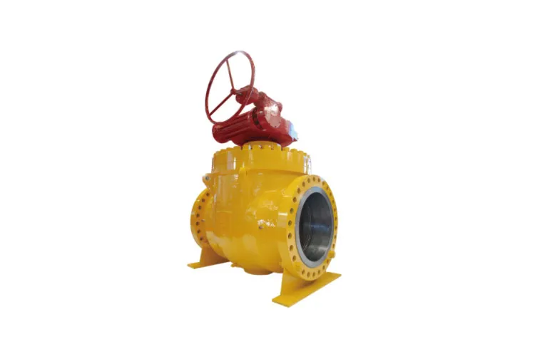
A trunnion mounted ball valve is a quarter‑turn valve in which the ball is supported by trunnions (upper and lower
stems or bearings) that hold the ball in a fixed position. The ball does not float downstream under pressure as in a Floating ball valve.
Instead, the trunnion design allows the seats to move towards the ball to achieve tight sealing.
1.1 Basic Construction
- Body – typically cast or forged steel, available in two‑piece or three‑piece constructions.
- Ball – precision‑machined, trunnion supported, often with hard‑faced or corrosion‑resistant coating.
- Trunnion – upper and lower support stems that absorb the loads from line pressure.
- Seats – spring‑loaded or pressure‑energized, soft‑seated or metal‑seated depending on service.
- Stem – drives the ball rotation (typically 90° from open to close) and connects to actuator or handle.
- Seals and gaskets – O‑rings, lip seals, and body gaskets to seal body joints, stem, and trunnion areas.
- Antistatic device – ensures electrical continuity between ball, stem, and body.
- Blow‑out proof stem design – prevents stem ejection in case of packing failure.
1.2 Typical Applications
- High‑pressure natural gas and crude oil pipelines.
- Block valves for transmission pipelines (pipeline isolation valves).
- Process isolation in refineries and petrochemical plants.
- LNG, LPG, and cryogenic service (with special design and materials).
- High‑temperature or abrasive services (with metal‑seated trunnion ball valves).
Trunnion mounted ball valves are preferred over floating ball valves when pressure, size, and torque become significant
(typically above DN 150 / NPS 6 or at higher pressure classes).
2. Key Features and Advantages of Trunnion Mounted Ball Valves
Understanding the inherent advantages of a trunnion mounted ball valve helps highlight why correct installation is critical.
The following table summarizes common benefits.
Feature |
Advantage |
Relevance to Installation |
Trunnion supported ball |
Lower operating torque and better stability at high pressure. |
Improper support or misalignment can overload trunnions and bearings. |
Spring‑loaded or pressure‑energized seats |
Reliable sealing even at low differential pressure. |
Incorrect installation direction may defeat double block and bleed design. |
Double block and bleed capability |
Allows isolation and verification of zero leakage through cavity bleeding. |
Wrong port orientation or blocked body cavity ports undermine safety functions. |
Fire‑safe design |
Metal‑to‑metal backup sealing in case of fire. |
Incorrect gasket selection, bolt torque, or body joint assembly can void fire‑safe performance. |
Blow‑out proof stem |
Enhanced safety during pressure surges and packing failures. |
Wrong installation orientation or stem side loading may compromise stem seals. |
Wide range of sizes and pressure classes |
Suitable for small bore to large pipeline block valves. |
Poor handling and lifting methods easily damage large diameter valves during installation. |
3. Typical Specifications and Standards
Trunnion mounted ball valves are designed and manufactured according to widely recognized international standards.
The following table lists common specification parameters for reference.
Parameter |
Typical Options / Ranges |
Notes |
Size range |
DN 50 to DN 1400 (NPS 2" to 56" and above) |
Large sizes are common as pipeline block valves. |
Pressure class |
ASME Class 150 to 2500; API 2000 to 15000 psi |
High pressure classes require careful installation and testing. |
Standards |
API 6D, API 608, ISO 14313, ASME B16.34 |
Follow design and testing requirements defined by these standards. |
End connections |
Flanged (RF, RTJ), butt‑weld, socket‑weld, threaded, hub‑type |
Each end type has specific installation precautions. |
Body materials |
Carbon steel, low‑temperature carbon steel, stainless steel, duplex, alloy steel |
Material choice must match fluid, temperature, and design code. |
Seat materials |
PTFE, RPTFE, PEEK, Nylon, metal‑seated designs |
Seat material impacts temperature and chemical compatibility. |
Temperature range |
Approx. -196°C to +450°C (cryogenic to high temperature) |
Depends heavily on body, seat, and seal material combination. |
Operation |
Manual lever/gear, pneumatic actuator, hydraulic actuator, electric actuator |
Actuator sizing and mounting are critical installation steps. |
Face‑to‑face dimensions |
ASME B16.10, API 6D standard patterns |
Important for piping layout and valve interchangeability. |
Testing |
API 6D, API 598, ISO 5208 hydrostatic and seat leakage tests |
Field testing should not exceed design test limits. |
4. Pre‑Installation Checklist for Trunnion Mounted Ball Valves
Many trunnion mounted ball valve installation mistakes originate from poor preparation.
Before installing any valve in the line, perform the following checks.
4.1 Documentation and Identification
- Verify valve tag, size, rating, material, and trim against the piping specification and line list.
- Confirm pressure class and temperature rating are suitable for the design conditions.
- Check certificates: material test reports, pressure test certificates, and compliance with API/ISO standards.
- Review the manufacturer’s installation, operation, and maintenance (IOM) manual thoroughly.
4.2 Visual and Functional Inspection
- Inspect body, flanges, and weld ends for damage, corrosion, or deformation.
- Check actuator, gear box, or lever for secure mounting and smooth operation.
- Verify open/close indication: fully open and fully closed positions should be clear and correct.
- Examine seat, ball surface, and sealing areas for debris, scratches, or foreign materials.
- Confirm that protective end caps and internal protections are present and only removed just before installation.
4.3 Storage and Handling
- Store valves in a clean, dry, vibration‑free area and keep end covers in place until installation.
- Use proper lifting points and lifting equipment; do not lift the valve by the actuator, stem, or handwheel.
- For large trunnion mounted ball valves, use slings around the body or manufacturer‑supplied lifting lugs.
Mishandling during storage and lifting is a frequent cause of trunnion damage, bent stems, and seat misalignment
even before installation starts.
5. Top Trunnion Mounted Ball Valve Installation Mistakes to Avoid
The following sections detail the most common and costly trunnion mounted ball valve installation mistakes,
along with recommended best practices.
5.1 Incorrect Flow Direction and Orientation
Many trunnion mounted ball valves are bidirectional, but some designs are unidirectional or have preferred flow direction.
A frequent installation mistake is ignoring the flow arrow or the seat design, which can compromise:
- Double block and bleed functionality.
- Seat sealing performance at differential pressure.
- Emergency sealant injection effectiveness.
Best Practices:
- Check body arrows or markings indicating “FLOW”, “INLET”, “OUTLET”, or “UPSTREAM SIDE”.
- Consult the datasheet to confirm whether the valve is truly bidirectional.
- Install the valve with the stem orientation as recommended (for example, stem at the top in horizontal pipelines).
- Avoid installing the stem underneath the pipeline in services where debris accumulation may occur.
5.2 Misalignment with Piping
Misalignment between the pipeline and trunnion mounted ball valve can cause:
- Excessive bending moment on the valve body and trunnions.
- Seat deformation and uneven sealing contact.
- Increased operating torque and early wear of bearings.
Best Practices:
- Ensure the pipe flanges or weld ends are properly aligned before positioning the valve.
- Use temporary supports and jacks to remove stress from the valve during alignment.
- Check alignment with feeler gauges and straight edges across flanges.
- Never use flange bolts to force misaligned pipe ends into position.
5.3 Inadequate Valve Support
Large and heavy trunnion mounted ball valves require dedicated supports.
A common mistake is assuming the adjoining pipe can support the full weight of the valve, actuator, and accessories.
Consequences include:
- Deflection leading to internal misalignment and seat leakage.
- Stress on flange welds or bolted joints.
- Vibration and fatigue in dynamic systems.
Best Practices:
- Provide independent valve supports or saddles as part of the piping design.
- Account for actuator weight, especially for large gear boxes or heavy electric actuators.
- Ensure supports allow for thermal expansion and contraction without overloading the valve.
5.4 Improper Gasket Selection and Flange Assembly
Incorrect gasket material or dimension is a recurring trunnion mounted ball valve installation mistake,
especially in high‑pressure and high‑temperature services.
- Using wrong gasket thickness may distort flanges.
- Incompatible gasket material can chemically degrade or extrude.
- Uncontrolled bolt tightening may cause gasket crushing or insufficient seating stress.
Best Practices:
- Match gasket material to fluid, temperature, and pressure class according to piping spec.
- Ensure gasket dimensions (ID, OD, thickness) match the flange standard (ASME B16.5, B16.47 etc.).
- Use a calibrated torque wrench and recommended bolt tightening sequence (cross pattern in multiple passes).
- Verify gasket centering between flanges before tightening.
5.5 Welding Damage to Seats and Seals
When installing butt‑weld end trunnion mounted ball valves, improper welding procedures can overheat the valve
and damage non‑metallic seats and seals. Mistakes include:
- Welding with the ball and seats in fully closed position, trapping heat.
- Failing to remove internal soft components when required by the manufacturer for high heat input welding.
- Not using thermal blankets or heat sinks around weld areas.
Best Practices:
- Follow manufacturer’s welding instructions exactly, including recommended ball position (often 50% open) during welding.
- For high heat procedures, remove seats and seals if specified and reinstall them afterwards using approved methods.
- Apply appropriate preheat and interpass temperature control to protect the valve internals.
- After welding, perform non‑destructive examination (NDE) and re‑test the valve if required.
5.6 Foreign Material and Contamination
Debris, welding slag, sand, and rust in the pipeline are a major cause of early seat damage and leakage.
Trunnion mounted ball valves with tight tolerances are especially vulnerable.
Typical Contamination-Related Issues:
- Seat surface scoring and extrusion.
- Ball surface scratches and pitting.
- Blockage of cavity relief or drain ports.
Best Practices:
- Clean the pipeline before valve installation: flushing, blowing, or pigging as required.
- Keep protective end caps on until the moment of installation.
- Do not use the valve as a temporary “blow‑off” device for cleaning pipes unless the design and manufacturer explicitly allow it.
5.7 Over‑torquing or Under‑torquing Bolts
Minimizing leakage at flange connections requires controlled bolt tightening. Installation mistakes include:
- Using power tools without torque control.
- Failing to re‑torque bolts after initial assembly and pressurization if specified by procedure.
- Ignoring lubricants or using inappropriate bolt lubricants.
Best Practices:
- Use manufacturer’s recommended torque values or piping class guidelines.
- Tighten bolts in a star or cross pattern in multiple passes (30%, 60%, 100% of target torque).
- For large diameter flanges, consider hydraulic tensioners as specified.
5.8 Incorrect Actuator Installation and Positioning
A trunnion mounted ball valve often uses gear boxes, pneumatic, hydraulic, or electric actuators.
Common actuator‑related installation mistakes include:
- Misalignment between valve stem and actuator drive.
- Using wrong keyway or adapter, causing stem damage.
- Setting travel stops incorrectly, leading to partial opening or closing.
- Failing to adjust limit switches and positioners after mounting.
Best Practices:
- Follow ISO 5211 or relevant mounting interface standards.
- Ensure actuator orientation allows easy access for maintenance and manual override.
- Set mechanical stops carefully so the ball is fully open or fully closed at the actuator extremes.
- Calibrate limit switches, position indicators, and positioners after installation.
5.9 Ignoring Cavity Relief and Double Block and Bleed Functions
Many trunnion mounted ball valves have automatic cavity pressure relief and double block and bleed (DBB)
capabilities. Installation errors include:
- Blocking body drain and vent ports with piping or insulation.
- Connecting drain ports to systems that cannot handle possible full line pressure.
- Not verifying cavity relief function during commissioning.
Best Practices:
- Keep body vent, drain, and injection fittings accessible for operation and maintenance.
- Route drains to safe and rated disposal systems, with proper valves and labeling.
- Test double block and bleed by closing the valve, bleeding the cavity, and verifying no leakage from either seat.
5.10 Skipping Functional and Leak Testing After Installation
Installing a trunnion mounted ball valve without proper pressure and functional testing increases the risk of hidden defects.
Mistakes include:
- Skipping seat leakage checks after welding or major mechanical work.
- Not verifying fail‑safe position of actuated valves.
- Relying solely on factory test certificates without in‑situ verification.
Best Practices:
- Carry out field hydrostatic or pneumatic tests according to relevant standards and project requirements.
- Cycle the valve several times under low pressure before full‑pressure testing to seat the seals.
- Verify actuator fails to the correct position (fail‑open, fail‑close, or fail‑in‑place) on power or air loss.
6. Orientation, Support, and Alignment Best Practices
6.1 Recommended Orientation
- Stem up orientation is typically preferred in horizontal pipelines to minimize debris accumulation around stem seals.
- For vertical pipelines, ensure that the manufacturer confirms acceptable flow direction and stem orientation.
- Avoid orientations that make body drains inaccessible or expose the actuator to extreme heat or splash zones.
6.2 Supporting Large Trunnion Mounted Ball Valves
Heavy valves require deliberate support design. The following table gives general guidance for support considerations.
Valve Size / Weight |
Typical Support Type |
Installation Notes |
Small to medium (up to approx. DN 150 / NPS 6) |
Pipe shoe or nearby pipe supports usually sufficient. |
Verify nozzle loads are within allowable limits; add local support if actuator is heavy. |
Medium to large (DN 200–DN 600 / NPS 8–NPS 24) |
Dedicated valve saddle, pedestal, or structural support frame. |
Consider thermal movement, access for operation, and lifting clearances. |
Very large (> DN 600 / NPS 24) |
Engineered structural steel supports with sliding or guided features. |
Input valve and actuator weights into stress analysis; follow recommendations for support locations and types. |
6.3 Alignment Tolerances
- Flange faces should be parallel within a small angular tolerance as defined by applicable construction codes.
- Centreline offset should be minimized to avoid bending stress transmitted to trunnions.
- Use alignment tools and proper fit‑up during field welding to keep tolerances within design limits.
7. Connection Types and Installation Considerations
7.1 Flanged End Trunnion Mounted Ball Valves
- Clean flange faces and check serrations or surface finish.
- Ensure gasket type matches raised face (RF) or ring‑type joint (RTJ) profile.
- Use correct bolt length considering gasket thickness and flange thickness.
- Avoid over‑tightening which can warp flanges or crush soft gaskets.
7.2 Butt‑Weld End Trunnion Mounted Ball Valves
- Confirm end preparation bevel angle and root gap meet WPS (welding procedure specification).
- Protect internal surfaces from spatter using purge dams or shields if necessary.
- Perform post‑weld heat treatment (PWHT) if required by material and design code.
7.3 Threaded and Socket‑Weld End Valves
- Use compatible thread sealant for threaded ends; avoid excessive sealant that can contaminate internals.
- Do not overtighten threaded joints; follow torque recommendations.
- For socket‑weld ends, leave correct expansion gap between pipe end and socket bottom to avoid stress after welding.
8. Actuation and Control System Pitfalls
8.1 Undersized or Oversized Actuators
Selecting actuators without considering actual operating torque can cause:
- Inability to fully close or open the valve at design pressures (undersized).
- Excessive forces leading to mechanical damage (oversized without proper stops).
Best Practices:
- Use valve torque data from the manufacturer, including safety factors and worst‑case scenarios (e.g., at minimum differential pressure for some designs).
- Consider service conditions: fluid type, temperature, frequency of operation, and potential scaling or deposits.
8.2 Incorrect Pneumatic/Hydraulic Hook‑Up
- Wrong port connections can reverse fail‑safe action (fail‑open vs fail‑close).
- Inadequate air or hydraulic supply pressure may not deliver full torque.
- No filters or regulators can lead to contamination and actuator malfunction.
Best Practices:
- Follow instrument hook‑up diagrams and P&IDs carefully.
- Install air filters, regulators, and lubricators as specified.
- Function test the actuator with and without line pressure applied.
8.3 Control System Calibration Errors
- Positioner not calibrated to match full stroke of the valve.
- Limit switches set at incorrect positions, causing false open/close signals.
- SCADA or control logic not aligned with actual valve fail position.
Best Practices:
- Calibrate positioners and limit switches using physical verification of valve position.
- Document as‑found and as‑left settings for future maintenance.
- Perform integrated testing with the plant control system before start‑up.
9. Commissioning, Testing, and Start‑Up Issues
9.1 Common Commissioning Mistakes
- Pressurizing the line too rapidly causing pressure shock on seats.
- Operating the valve under partial opening as a throttling device when it is designed only for on/off service.
- Failing to bleed trapped air or gas from the valve cavity before hydrostatic testing.
9.2 Recommended Testing Procedures
Test Type |
Purpose |
Key Considerations |
Hydrostatic shell test |
Verify body integrity under pressure. |
Do not exceed maximum allowable test pressure. Follow depressurization procedures. |
Seat leakage test |
Check sealing performance of upstream and downstream seats. |
Test both directions of pressure if valve is bidirectional; record leak rates per API or project criteria. |
Functional cycling test |
Confirm smooth operation and actuator performance. |
Cycle valve several times; observe torque, noise, or sticking behavior. |
Double block and bleed test |
Validate DBB capability and cavity relief. |
Close valve, open body bleed, monitor for pressure increase or leakage. |
9.3 Start‑Up Best Practices
- Increase line pressure gradually, monitoring for leaks at flanges, body joints, packing, and injection fittings.
- Avoid throttling with a trunnion mounted ball valve unless it is specifically designed for control service.
- Monitor actuator performance during initial operating cycles; check for excessive vibration or noise.
10. Maintenance, Operation, and Lifecycle Mistakes
Even after correct installation, certain operational practices can shorten the life of a trunnion mounted ball valve.
10.1 Using On/Off Valves for Throttling
- Standard trunnion mounted ball valves are primarily designed for full open/full close service.
- Throttling can lead to erosion of seats and high vibration at the ball edge.
10.2 Ignoring Seat and Stem Seal Injection Systems
- Emergency sealant injection fittings are often provided for temporary restoration of sealing.
- Failing to maintain these fittings (plugging, corrosion) can render them useless in emergencies.
Best Practices:
- Inspect and exercise injection fittings periodically.
- Use only compatible injection sealant recommended for the valve type and service.
10.3 Poor Periodic Inspection
- Not checking packing leaks at stem and trunnion seals.
- Ignoring small external leaks which may grow under pressure and temperature cycling.
- Over‑tightening packing in an attempt to eliminate leakage, increasing stem torque and wear.
Best Practices:
- Adopt a periodic inspection schedule aligned with plant maintenance plans.
- Adjust packing following manufacturer torque or compression recommendations.
- Record valve operating torque trends; a rising trend may indicate internal wear or contamination.
11. Installation and Inspection Checklists
The following concise checklists help reduce trunnion mounted ball valve installation mistakes on site.
11.1 Pre‑Installation Checklist
Item |
Check |
Valve specification |
Size, rating, materials, and end connections match piping specification. |
Documentation |
IOM manual, test certificates, and MTRs verified. |
Visual inspection |
No visible damage, corrosion, or missing parts. |
End protection |
End caps intact and removed only just before installation. |
Operation check |
Valve cycles smoothly from fully closed to fully open. |
Markings |
Flow direction, stem position, and pressure rating markings clearly visible. |
11.2 Installation Checklist
Stage |
Key Actions |
Piping preparation |
Align pipes, clean internal surfaces, and verify flange or weld end condition. |
Positioning |
Orient valve correctly with respect to flow direction and stem orientation. |
Support |
Install or confirm adequate supports for valve and actuator. |
Gasketing |
Select and install correct gasket type and dimensions. |
Bolt tightening / welding |
Apply correct torque sequence or qualified welding procedure. |
Actuator mounting |
Verify alignment, set stops, calibrate indicators and limit switches. |
11.3 Post‑Installation and Commissioning Checklist
Check |
Verification |
Leak test |
No visible leaks at flanges, packing, body joints, or injection fittings at test pressure. |
Functional test |
Valve cycles fully and smoothly; actuator and indicators respond correctly. |
DBB / cavity relief |
Double block and bleed valves pass cavity isolation test where applicable. |
Support integrity |
Supports stable without excessive vibration during operation. |
Documentation |
As‑built orientation, tag numbers, and test results recorded for future reference. |
12. Frequently Asked Questions About Trunnion Mounted Ball Valve Installation
12.1 Are trunnion mounted ball valves always bidirectional?
Not always. Many designs are bidirectional, but some have preferred flow direction or are unidirectional due to
seat design, cavity pressure relief, or double block and bleed functionality. Always check the valve documentation and body markings
to avoid the mistake of installing a unidirectional trunnion mounted ball valve in reverse.
12.2 Can a trunnion mounted ball valve be installed vertically?
Yes, but only if the manufacturer confirms acceptable performance in vertical orientation. Issues such as debris accumulation,
gravity effects on seats, and actuator mounting should be considered. Improper vertical installation can lead to uneven wear or
unexpected torque increases.
12.3 Is it safe to weld a trunnion mounted ball valve in the line?
Many butt‑weld trunnion mounted ball valves are designed to be welded in place, provided the correct welding procedure is followed.
Never assume; consult the IOM. Excessive heat input is a common installation mistake that damages seats and seals.
Some designs require partial opening of the ball or even temporary removal of internal soft parts before welding.
12.4 Can trunnion mounted ball valves be used for throttling?
Standard trunnion mounted ball valves are typically on/off isolation valves.
Using them for throttling can cause cavitation, erosion, noise, and accelerated wear. If throttling duty is required,
a control‑grade trunnion ball valve or a dedicated control valve should be selected.
12.5 How often should trunnion mounted ball valves be cycled?
Cycling frequency depends on process duty and plant maintenance philosophy. For rarely operated isolation valves,
periodic cycling during maintenance windows is recommended to prevent sticking, deposit build‑up, and seal adhesion.
Neglecting this can make future operation difficult, requiring higher torque or even mechanical intervention.
13. Conclusion
Correct installation of a trunnion mounted ball valve is essential for safe, leak‑free, and reliable operation in
demanding industrial and pipeline applications. The most frequent trunnion mounted ball valve installation mistakes
include poor alignment, inadequate support, incorrect orientation, welding damage, contamination, improper actuator mounting,
and incomplete testing.
By following the checklists, best practices, and technical recommendations outlined in this guide, engineers and plant operators can:
- Improve sealing performance and extend valve service life.
- Reduce unplanned shutdowns caused by valve failure.
- Enhance safety by maintaining proper double block and bleed and cavity relief functions.
- Optimize total lifecycle cost for critical isolation valves.
Every installation should be validated against the specific manufacturer’s documentation, relevant standards such as API 6D and ASME B16.34,
and project‑specific piping specifications. Investing time in proper installation and commissioning is significantly less costly than
dealing with valve failure or leakage in high‑pressure, high‑value process systems.
“`








 Phone