
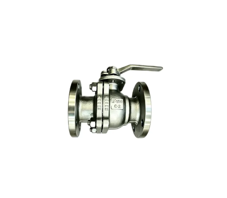
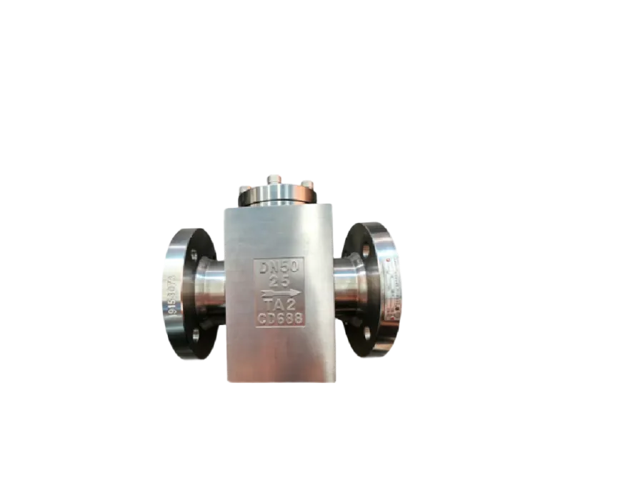
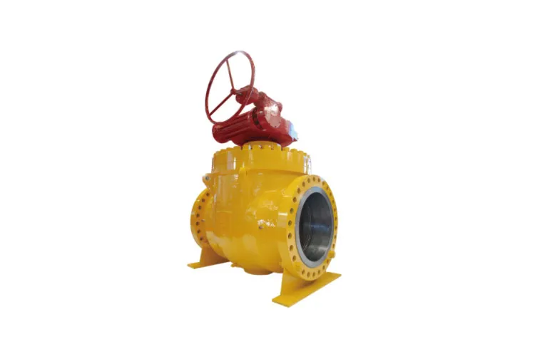



Fixed Ball Valve Safety Features Explained
Fixed ball valves, more commonly referred to as trunnion-mounted ball valves, are widely used in pipelines and process systems where safety, leak-tightness, and reliability are critical.
This comprehensive guide explains the key fixed ball valve safety features, their design principles, and how they contribute to safer operation in demanding industrial environments.
This article is written in clear technical English, structured for SEO performance and user readability. It can be used directly as content for a blog, directory page, or industry landing page focused on fixed ball valve safety.
A fixed ball valve is a type of ball valve in which the ball is mechanically supported by trunnions at the top and bottom.
Unlike a Floating ball valve where the ball moves slightly downstream to seal, the ball in a fixed (trunnion-mounted) design is held firmly in position.
Sealing is achieved by spring-loaded or pressure-energized seats that move toward the ball.
| Feature | Fixed (Trunnion-Mounted) Ball Valve | Floating Ball Valve |
|---|---|---|
| Ball Support | Ball supported by trunnions at top and bottom | Ball supported only by seats; free to move slightly |
| Sealing Principle | Seats move toward fixed ball (spring-loaded or pressure-energized) | Ball moves against downstream seat under line pressure |
| Typical Size Range | Medium to very large sizes (DN 50 and above, often much larger) | Smaller to medium sizes (commonly up to DN 200 / 8″) |
| Operating Torque | Lower torque for large sizes due to trunnion support | Higher torque at larger sizes and higher pressures |
| Applications | High-pressure, large-bore, critical service (oil & gas, petrochemical, pipeline) | General-purpose, lower to medium pressure applications |
| Leak-Tightness | Excellent sealing in both directions; suitable for double block and bleed | Good sealing but often optimized for unidirectional service |
| Cost | Generally higher due to complex construction | Generally lower; simpler design |
In these applications, safety features such as anti-blow-out stems, fire-safe design, anti-static devices, emergency sealant injection, and double block and bleed capability are essential.
The following sections explain these safety features in detail.
The safety philosophy behind fixed ball valves is to provide:
Designers achieve these goals by combining mechanical safety features, material selection, and compliance with international standards.
Common standards affecting fixed ball valve safety include:
Below is an overview of essential fixed ball valve safety features usually considered in design, engineering, and specification.
| Safety Feature | Primary Safety Function | Typical Relevance |
|---|---|---|
| Anti-Blow-Out Stem | Prevents stem ejection under pressure | Personnel safety, containment |
| Fire-Safe Design | Maintains basic sealing after a fire | Process containment, environmental safety |
| Anti-Static Device | Dissipates electrical charges | Explosion protection in flammable media |
| Double Block and Bleed (DBB) | Allows isolation and cavity pressure check | Maintenance safety, positive isolation |
| Emergency Sealant Injection | Restores sealing in case of seat or stem leakage | Operational safety, contingency measure |
| Self-Relieving Seats | Protects against overpressure in valve cavity | Body integrity, sealing safety |
| Blow-Down / Vent / Drain Connections | Controlled depressurization and draining | Safe maintenance and isolation |
| Locking Device / Position Indication | Prevents accidental operation, confirms position | Operational and personnel safety |
| Fugitive Emission Control | Reduces stem and body joint emissions | Environmental compliance, long-term safety |
| Blow-Out Resistant Seats & Seals | Prevents internal component ejection | Integrity under pressure and flow |
One of the most critical fixed ball valve safety features is the anti-blow-out stem.
This design ensures that the valve stem cannot be ejected from the body under internal pressure, even if external components such as gland bolts or packing fail.
| Element | Typical Design Approach | Safety Impact |
|---|---|---|
| Stem Shoulder | Machined step larger than stem hole in body | Provides mechanical stop against blow-out |
| Retainer Ring | Metal ring installed from inside or outside | Supports stem under pressure, resists axial load |
| Body/Bonnets Geometry | Designed so pressure pushes stem into seat | Pressure-assisted anti-blow-out function |
| Stem Material | High-strength alloy steel or stainless steel | Prevents mechanical failure under load |
Many fixed ball valves are specified as fire-safe, meaning they maintain a basic sealing capability during and after a fire.
Fire-safe design is usually validated by tests according to API 607 or ISO 10497.
| Component | Fire-Safe Feature | Function During Fire |
|---|---|---|
| Seats | Secondary metal-to-metal seating surface | Provides sealing when soft seat inserts are burned |
| Stem Packing | Graphite packing, fire-resistant gland design | Maintains stem sealing at high temperatures |
| Body Gaskets | Spiral-wound or graphite-based gaskets | Resist destruction by fire, limit external leakage |
| Anti-Blow-Out Stem | Mechanical retention independent of soft parts | Prevents stem ejection when packing burns |
| Fire-Safe Test Certification | Tested according to ISO 10497 / API 607 | Ensures design proven under standardized fire scenarios |
A properly designed fire-safe fixed ball valve ensures that, even in a severe fire, catastrophic release of flammable fluid is minimized, supporting overall facility safety.
In ball valves handling flammable fluids or gases, static electricity can build up due to friction between the ball, seats, and fluid flow.
An anti-static device is installed to ensure a continuous electrical path to ground, preventing static discharge that could ignite the medium.
| Location | Component | Function |
|---|---|---|
| Ball–Stem Interface | Metal spring or graphite brush | Provides conductive path from ball to stem |
| Stem–Body Interface | Metal spring, pin, or grounding ring | Ensures continuity from stem to valve body |
| Body–Piping Interface | Metallic connection to pipeline | Dissipates charges to ground through piping system |
An important safety and operational feature of many fixed ball valves is the ability to provide double block and bleed (DBB).
This allows positive isolation and verification that no leakage passes through the valve.
| Feature | DBB (Double Block and Bleed) | DIB (Double Isolation and Bleed) |
|---|---|---|
| Definition (Typical) | Two seating surfaces in series, with bleed between | Two isolation barriers in series, both capable of sealing in same direction |
| Self-Relieving Seats | Usually self-relieving to upstream side | May not be self-relieving; relies on external relief |
| Application | Pipeline isolation, on/off duty | High-integrity isolation, critical process boundaries |
| Safety Impact | Ensures valve can be tested for tight shutoff | Provides enhanced isolation for hazardous service |
Many fixed ball valves, especially in pipelines and critical services, are equipped with sealant injection fittings on the stem and seats.
This emergency sealing system allows operators to restore sealing temporarily in case of damage or wear of primary seals.
| Location | Purpose | Comments |
|---|---|---|
| Seat Injection Fitting | Temporary seal between seat and ball / seat and body | Used when seat leakage is detected during operation |
| Stem Injection Fitting | Auxiliary sealing around stem packing | Used in case of stem leakage to atmosphere |
Although the emergency injection system is a valuable safety feature, it is not a substitute for proper maintenance.
It should be considered a short-term safety and reliability enhancement to manage unforeseen issues.
In a fixed ball valve, when the valve is closed, the fluid trapped in the body cavity may experience thermal expansion, resulting in overpressure.
To mitigate this, many designs incorporate self-relieving seats or separate pressure relief devices.
A complete fixed ball valve safety concept includes provisions for venting, draining, and flushing the body cavity.
These assist in safe maintenance and isolation practices.
| Connection Type | Function | Safety Contribution |
|---|---|---|
| Vent (Top) | Release trapped gas or vapor from body cavity | Prevents uncontrolled release when opening valve or body |
| Drain (Bottom) | Remove liquid or sediment from body cavity | Allows safe draining before maintenance |
| Flushing Ports | Introduce cleaning fluids through cavity | Removes corrosive or hazardous residues |
| Sealant Injection | Inject emergency sealing compound | Restores temporary sealing capability |
Prevention of inadvertent operation is another key aspect of fixed ball valve safety.
Locking devices and clear position indication help ensure that the valve remains in the desired position and that operators can confirm open/closed status at a glance.
| Type | Description | Safety Impact |
|---|---|---|
| Visual Indicator | Arrow or pointer on top of the stem indicating open/close | Helps field operators verify valve status quickly |
| Limit Switches | Electrical switches for remote indication | Allows control room monitoring and interlocking |
| Mechanical Flag Indicator | Flag raised or lowered according to position | Useful in low-light or remote installations |
Fixed ball valves often operate in systems where control of fugitive emissions is required by regulation.
Reducing leakage through the stem and body joints improves both environmental safety and long-term sealing performance.
To understand fixed ball valve safety features, it is useful to look at the main components and how each one contributes to overall safety.
| Component | Function | Related Safety Aspect |
|---|---|---|
| Body | Primary pressure-containing shell | Designed for pressure rating, corrosion allowance, fire resistance |
| Ball | Rotating element controlling flow | Surface finish and coatings affect sealing and erosion resistance |
| Trunnions | Support ball top and bottom | Reduces operating torque, stabilizes ball under pressure |
| Seats | Provide sealing between ball and body | Soft/metallic inserts, fire-safe secondary seats, self-relieving design |
| Stem | Connects actuator/handle to ball | Anti-blow-out design, anti-static path, stem sealing |
| Packing | Seals around stem to prevent external leakage | Low-emission materials, fire-safe design, live-loading |
| Body Gaskets | Seal body joint (one-piece, two-piece, or three-piece construction) | Fire-safe materials, high-integrity sealing |
| Actuator / Gear Box | Provides torque to operate valve | Over-torque protection, failsafe position with spring return actuators |
| Auxiliary Ports | Vent, drain, injection, instrumentation | Safe depressurization, emergency sealing, monitoring |
Material selection significantly affects the safety and reliability of fixed ball valves, especially in corrosive, high-temperature, or low-temperature service.
| Part | Common Materials | Safety-Related Characteristics |
|---|---|---|
| Body | Carbon steel (A105, A216 WCB), low-temperature carbon steel, stainless steel (CF8M, CF3M), duplex, alloy steels | Strength, toughness, corrosion resistance, temperature capability |
| Ball | Stainless steel, nickel-plated or hard-coated carbon steel, duplex or super duplex | Wear resistance, corrosion resistance, smooth sealing surface |
| Seats | PTFE, reinforced PTFE, PEEK, nylon, metal seats with overlays (Stellite, hard-facing) | Sealing reliability, temperature/chemical resistance, fire performance |
| Stem | Stainless steel, high-strength alloy steels | Mechanical strength, resistance to stress corrosion cracking |
| Packing / Gaskets | Graphite, PTFE, expanded PTFE, composite gaskets | Leak tightness, fire resistance, fugitive emission control |
Safety requires that the pressure-temperature rating of the valve is appropriate for the service.
This is typically defined by standards such as ASME B16.34 and material group.
Beyond static design features, operating aspects of fixed ball valves also contribute to safety.
Correct sizing of actuators, consideration of fail-safe positions, and torque margins are crucial.
| Fail-Safe Strategy | Description | Typical Use Case |
|---|---|---|
| Fail-Closed | Valve moves to closed position on loss of power/air | Isolating hazardous fluid or stopping flow in emergency |
| Fail-Open | Valve moves to open position on loss of power/air | Ensuring cooling flow or relief path is maintained |
| Fail-in-Place | Valve stays in last position on power/air loss | Applications where sudden change in flow is dangerous |
For fixed ball valves in critical services, the selection of fail-safe position is part of process hazard analysis and overall plant safety design.
The following example specifications list typical parameters considered when selecting or specifying a trunnion-mounted fixed ball valve from a safety perspective.
Values are indicative and vary according to standards, materials, and application.
| Parameter | Typical Options / Requirements |
|---|---|
| Valve Type | Fixed (Trunnion-Mounted) Ball Valve, Side-Entry or Top-Entry |
| Size Range | DN 50 to DN 1200 (NPS 2″ to 48″ or larger) |
| Pressure Class | ASME Class 150 to 2500 or API 2000–10000 as applicable |
| Body Materials | Carbon steel, low-temperature carbon steel, stainless steel, duplex, others |
| Seat Type | Soft-seated (PTFE/RTFE/PEEK) or metal-seated with fire-safe secondary seat |
| Design Standard | API 6D, API 608, ASME B16.34, ISO 14313 or equivalent |
| End Connections | Flanged (ASME B16.5), butt-welded (ASME B16.25), others |
| Fire-Safe Design | Compliant with ISO 10497 / API 607 |
| Anti-Blow-Out Stem | Mandatory, blow-out proof stem with shoulder or retainer |
| Anti-Static Device | Mandatory for flammable service, ball–stem–body continuity |
| DBB Function | Double block and bleed capability via cavity bleed port |
| Cavity Relief | Self-relieving seats or body pressure relief device |
| Stem Sealing | Low-emission packing, multiple rings, live-loading optional |
| Fugitive Emission Class | ISO 15848 or TA-Luft where required |
| Auxiliary Connections | Vent, drain, and emergency sealant injection as per specification |
| Actuation | Manual, gear-operated, or automated (pneumatic, hydraulic, electric) |
| Locking / Indication | Locking device, clear open/close position indication |
Inspection and testing regimes validate that fixed ball valves meet safety requirements before service.
Typical tests include:
| Test Type | Purpose | Related Standards |
|---|---|---|
| Hydrostatic Shell Test | Checks body strength and leak-tightness | API 6D, API 598, EN 12266-1 |
| Seat Leakage Test | Verifies shutoff capability | API 6D, API 598, ISO 5208 |
| Fire-Safe Test | Ensures sealing under fire | ISO 10497, API 607 |
| Fugitive Emission Test | Determines emission rate from stem/body | ISO 15848, EPA-based methods |
| Operational Torque Test | Confirms torque is within actuator capacity | Manufacturer / project specifications |
Fixed ball valves are used in many different services, each with unique safety considerations.
Some typical applications include:
The specific design of fixed ball valves offers several inherent safety advantages over other valve types and floating ball valves in certain applications.
| Valve Type | Key Safety Benefits | Typical Limitations |
|---|---|---|
| Fixed (Trunnion) Ball Valve | High-integrity shutoff, DBB, low torque, versatile safety features | More complex design, higher initial cost |
| Floating Ball Valve | Simple design, good shutoff in small sizes | Higher torque at large sizes, limited DBB capability |
| Gate Valve | Bidirectional sealing, suitable for isolation | Slow operation, potential seat wear, not quarter-turn |
| Plug Valve | Good for throttling and dirty service | Higher torque, possible lubrication requirements |
To fully benefit from built-in fixed ball valve safety features, proper selection, installation, operation, and maintenance are essential.
Fixed (trunnion-mounted) ball valves combine mechanical robustness with a comprehensive set of safety features that make them ideal for critical industrial services.
Key elements include:
When correctly specified, installed, and maintained according to recognized standards and best practices, fixed ball valves provide a high level of safety, reliability, and operational control in pipelines and process plants worldwide.
“`
الشخص المسؤول: ماكس سونغ (سونغ شانشان)
المنصب: المدير العام
الجوال: +86 15611322632
الهاتف: +86 10 89282693
البريد الإلكتروني: international@bvmc.com
العنوان: رقم 3، طريق لوهي، بلدة بانغتشوانغ، حي داكسينغ، بكين


حقوق الطبع والنشر © شركة مصنع بكين للصمامات المحدودة
خريطة الموقعيستخدم هذا الموقع ملفات تعريف الارتباط لضمان حصولك على أفضل تجربة على موقعنا.



 Phone